Browse Our Products:
HLC - Hydraulic Lever Clamp

Features:
- A safe, quick and simple way to clamp dies, workpieces and fixtures
- Easily inserted into existing T-slots, adapts to any die width
- Allows semi-automated die change operation
- Hydraulic activation assures quick and effortless clamping
- Generous piston stroke allows for variations in die shoe thickness
- Compact jaw design requires minimal clamping surface
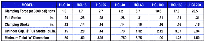
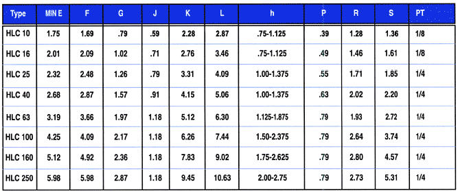
Technical Data
Notes:
- Clamping strokes and full strokes are for standard models; custom strokes available on request.
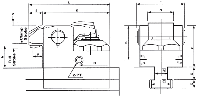
- Dimensions A, B, C and D determined by T-slot dimensions.
- Specify T-slot dimensions (a, b, c, d) and clamping height (h) when ordering.
- Specify dimension "h" down to 0.20" increments.
- Clamps with a dimension greater than Max. hare also optionally available.
Operating Procedure:
- Visually inspect clamp for obvious defects and make certain that the hydraulic power supply is disactivated and that the clamp jaw is fully tipped back (hydraulic piston is its retracted position).
- Place clamp into T-slot.
- Push clamp forward (toward die) as far as possible to ensure proper seating. Make certain that the die shoe surface is free of debris and lubricants.
- Inspect the gap between the clamping jaw and the die surface to ensure that it does not exceed the full stroke of the clamp. WARNING: Clamp will not generate clamp force if gap exceeds the full stroke.
- Activate hydraulic supply.
To Unclamp - Reverse procedure.
Ordering Information
When ordering or requesting a quote, please take a few minutes to complete the following data sheet.

Necessary Data
Range of die shoe thickness: ________ min. ________ max.
(min. and max. values must be with in .25" of each other)
Press tonnage: ________
Weight of dies: ________ top ________ bottom
Clearance between ram and bolster (shut height): ___________
T-Slot Dimensions
If standard: ________
If non-standard:
Width of throat (A) _______
Depth of throat (B) _______
Width of head (C) _______
Depth of head (D) _______
