HBS
Hydro-Mechanical Block Clamp
Area of application
The hydro-mechanical block clamp unit type HBS is designed for medium-sized and large presses exerting a pressure of ca. 500 tons upwards. It is particularly suitable for bottom die clamping and rolling bolster clamping. It is also being used increasingly for top die clamping.
The clamp unit can be fixed to the bed or ram surface or on the inside of the press frame in the case of bolster clamping.
Its use requires dies that have straight clamping edges.
Mode of operation
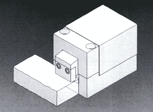
A hydraulically actuated mechanically locking clamping wedge mechanism transmits its clamping force to a clamping jaw.
In the clamping process, the jaw is forced out of the housing, and clamps the die to the surface of the bed or the slide. The movement sequence is internally controlled.
Movement sequence for applying the clamping force:
- Driving out the clamping jaw up to a point above the clamping edge of the die
- Clamping movement of the clamping jaw. (release of the clamp unit in reverse order)
Distinguishing features
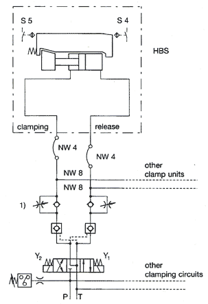
The clamp unit is fitted with a clamping wedge mechanism. In this system, the clamping force required is transmitted by mechanical components which are actuated by low hydraulic pressure only during the clamping or release process. The clamping wedge mechanism ensures that the clamp unit is mechanically self-locking when clamping. Nevertheless, a pilot-controlled non-return valve in both the clamping and release ports must secure the clamp unit against vibrations occurring during the production process. Thus, the hydraulic power unit can be switched off in clamped or released condition. Because of this, the clamping force is independent of the compressibility of the compression media, the operating temperatures and the line losses.
In the parked position, the clamping jaw is completely retracted into the housing, and thus protected from damage. The clamping edge of the die is released, and changing dies without interference is assured.
In the case of the dies used, maximum thickness tolerances of ±1.0 mm are permitted.
Electrical control of the following functions (switches):
- Jaw in clamping position (S4)
- Jaw in retracted position (S5)
- Pressure controls by means of a pressure switch on the hydraulic unit advisable.
Advantages
- Mechanical self-locking
- Occupies little space, due to compact dimensions
- Large clamping thickness tolerance
- Central control
- Hydraulic pressure required only during the clamping or re lease process
- High mechanical load capacity
Construction
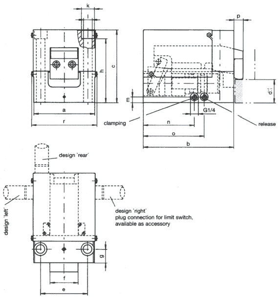
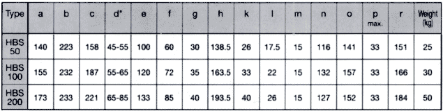
The individual components of the clamp unit are made from high-strength steels. The element is secured by two bolts of strength class 10.9 (not included). The thread dimension depends on the type (see technical drawing).
Technical data
| Type | HBS 50 | HBS 100 | HBS 200 | |
| Nominal clamping force | kN | 50 | 100 | 200 |
| Max. load capacity | kN | 80 | 160 | 320 |
| Max. operating pressure | bar | 110 | 110 | 110 |
| Die thickness tolerance | mm | ± 1.0 | ± 1.0 | ± 1.0 |
| Oil volume required (each process) clamping | cm3 | 12 | 54 | 58 |
| Oil volume required (each process) release | cm3 | 20 | 79 | 73 |
| Delivery rate per element | l/min. | 0.2-0.3 | 0.6-1.2 | 0.6-1.2 |
| Weight | kg (ca.) | 25 | 30 | 50 |
| Hydraulic connections | G 1/4 | G 1/4 | G 1/4 | |
| Max. operating temperature | °C | 70 | 70 | 70 |
| Pressure medium | Hydraulic Oil Standard 3448 ISO Vce (DIN 51519) |
|||
| Viscosity | 25 - 60 cST/40 °C | |||
| Filter | 20 - 25 µm | |||
1) If a pump with a higher delivery rate than necessary is used, the oil flow must be reduced
by means of flow regulating valves or oneway restrictors.
Precision position switches
- 2 inductive proximity switches
- PNP contact